Custom Game Engine
During my second year at TGA my team and I built our own game engine in C++ using DirectX 11.

Volumetric Fog
When light travels through fog it scatters in random directions. Read about how I simulated this in my custom built game engine.

SSAO
SSAO gives all 3D-objects in a scene a relationship with each other, creating depth and realism.
Group Projects
A collection of group projects I have contributed to.
Custom Game Engine
During my second year at The Game Assembly, my team and I developed a custom game engine named Kitty Engine for a total of 4 group projects. This page goes more in depth on some of my contributions on the engine. Full project can be found here: Kitty Engine source code
[Disclaimer] The source code was moved from a private perforce server to github so all previous commit history has thus been deleted. On the other hand there is a game project in the repo. The game can be played here: Intergalactic Ball Throwing Championship With Friends ツ
GameObject Component System
When we first started building the engine, I took on the responsibility of writing the code that handles the logic side of the game. This includes handling scenes, updating objects and running game specific code in a structured way. After some researching and discussions in the team I took the decision to build a GameObject/Component system that is familiar to Unitys scripting interface. I chose to design it this way since we all had previous experience with Unity and would therefor feel familiar and intuitive. This part of the engine works as following: an object called SceneManager owns all scenes of the game and is responsible to run the current scenes update functions, changing scene and lastly loading a new scene from file. The Scene object contains everything that an instance of a level should have, this includes a GameObject Manager, an interface to the collision system and a navmesh. GameObject Manager owns and runs all the GameObjects of the scene. These objects are the game specific objects that needs to be updated frequently. The manager handles the order of execution of the GameObjects functions and is also the interface for GameObjects to be able to reach other GameObjects and its Components. The GameObject is a more complex class. Although it has some member variables to its name it is the member functions that is the core of the class together with its components. These functions all have a very specific purpose that is used to call the function with the same name in the GameObjects Components. The Component is the bottom of the pyramid. Just as in Unity these objects have a certain purpose defined by the programmer. Together with GameObjects, Components defines the object it is owned by. A PlayerController could for instance have a PlayerComponent, ColliderComponent and a MeshComponent to define itself and its behaviours.
class Component
{
public:
  virtual ~Component() {};

  virtual void SetData(void* aDataObject = nullptr) { aDataObject; };
  virtual void DefaultData() { __noop; }

  inline virtual void SetActive(const bool aValue)
  {
      isActive = aValue;

      isActive ? OnEnable() : OnDisable();
  };

  inline bool IsActive() const { return isActive; };

  inline GameObject& GetGameObject() { return myGameObject; };
  inline const GameObject& GetGameObject() const { return myGameObject; };
protected:
  friend class GameObject;

  ///// Update Loop Handling /////
  virtual void Awake() { __noop; };
  virtual void LateUpdate() { __noop; };
  virtual void EarlyUpdate() { __noop; };
  virtual void Update() { __noop; };

  ///// Activity Handling /////
  virtual void OnEnable() { __noop; };
  virtual void OnDisable() { __noop; };
  virtual void OnDestroy() { __noop; };


  ///// Collision Handling /////
  virtual void OnTriggerEnter(const CollisionData& aCollisionData) { __noop; aCollisionData; };
  virtual void OnTriggerStay(const CollisionData& aCollisionData) { __noop; aCollisionData; };
  virtual void OnTriggerExit(const CollisionData& aCollisionData) { __noop; aCollisionData; };

  virtual void OnCollisionEnter(const CollisionData& aCollisionData) { __noop; aCollisionData; };
  virtual void OnCollisionStay(const CollisionData& aCollisionData) { __noop; aCollisionData; };
  virtual void OnCollisionExit(const CollisionData& aCollisionData) { __noop; aCollisionData; };

  virtual void OnPhysXCollision(const PhysXCollisionData& aPhysXCollisionData) { __noop; aPhysXCollisionData; };


  /* Is called right when GameObjectManager destroys all other gameobjects. */
  virtual void OnSceneChange() { __noop; };

  ///// Debug /////

  virtual void DrawDebug(KE::DebugRenderer& aDbg) { __noop; };
  virtual void Inspect(KE_EDITOR::ComponentInspector& aInspector) { __noop; };

  Component(GameObject& aParentGameObject) : myGameObject(aParentGameObject) {};

  GameObject& myGameObject;

  bool isActive = true;
};
The first iteration of this system saw a pure virtual component class, but this had a major drawback. Pure
virtual forces a derived class to implement ALL of the base component class’s virtual functions, which
most of the time meant a bunch of empty function calls and cluttered files. My solution to this was to
instead let the base class have a body defined in all function with the intrinsic __noop in
all of them. This makes sure that the function is ignored and no code is generated if it’s not overridden
by the derived class. When we ran 15000 GameObjects with and without the __noop intrinsic we
saw that the difference went from 1.16ms with it active to 2.29ms without it.
Reflections
Overall I am very pleased with how well the system has held up over 4 game projects, especially with the complexity of some of the projects in mind. But of course it has its limits and is far from perfect. Working on this has taught me a lot on the importance of good memory management and how a small change can lead to a large problem. Since the system can handle >15000 GameObjects with probably even more components at the same time, it became important to be mindful about not adding unnecessary member variables to the class. There are some optimizations I would like to implement, one of them being a solution to the lack of memory management. A system like ECS is famous for its cache friendliness, something that is not really utilized in this system. Both GameObjects and Components are created on demand and allocated on the heap randomly. One solution to this would be to create a custom allocator that can organize both GameObjects and components so that they are placed linear in memory. This would increase performance when iterating through the components when updating them.
Deferred Renderer
What is Deferred Rendering?
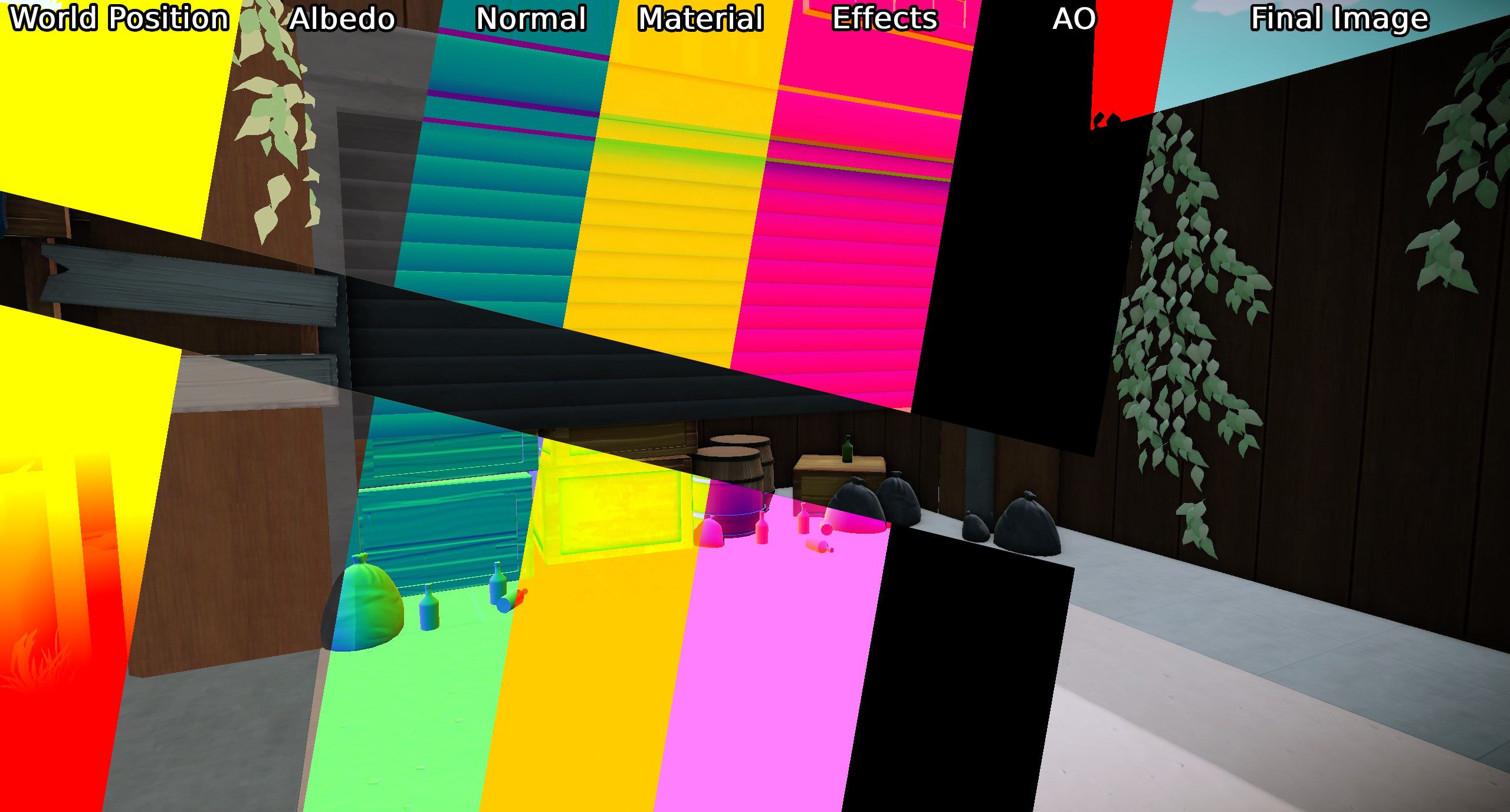
During the second project with the engine we wanted to go from a forward renderer to a deferred renderer, so together with Anton Eriksson I took on this task. Deferred rendering is a technique that dissects the data to be rendered and writes what data should be used per pixel to different textures, instead of forward rendering that renders all objects as you would create a stop motion movie with paper figures. Another huge difference from forward rendering is that instead of running expensive shader code on objects that will later be occluded by something in front, we just run the expensive shaders later when we have determined what data is to be used on that pixel. In our deferred renderer we chose to extract the following data from our rendered models: World Position, Albedo, Texture Normal, Material, Ambient Occlusion and lastly Effects. Although the world position texture can be seen as redundant as we could just as easily calculate the world position in the shader, we agreed that it has its benefits to keep the texture. These textures are saved in an object called GBuffer that acts as a texture container for the Deferred Renderer. When all models have been rendered we are left with several textures that contain their relevant data, now its just up to something to put them all together.
Putting it together
So how do we put the textures together and create the final image? Some sources proposes that a fullscreen shader is to be used to put everything together in the right place, but we also want the scene to be lit and that data hasn’t been accounted for when writing to the albedo (colour) texture. In our previous renderer we ran all of the lighting code in each models pixel shader, but as previously mentioned this lead to some objects being shaded that would later be overwritten. Since the Directional Light is omnipresent in the scene we might as well use a fullscreen shader to apply it. “Aha!”, you say, then maybe we can also try to create an image from the GBuffer-textures at the same time, and that’s exactly what we did! We are left with an image that has all the texture information given from the model as well as lighting information from the directional light. Even though it would work, it wouldn’t be efficient to apply point or spotlights with a fullscreen shader since they more often then not don’t cover the whole screen. The solution we went with was to generate a low poly sphere that covers the size of the light. For every light we just move the sphere to where that light is in world space and renders it as a normal 3D-mesh with its own pixel shader. The sphere works like a mask would in a program like Photoshop, essentially it only manipulates the pixels that the sphere covers and nothing else. When rendered the result is then applied to the image given by the directional lights fullscreen shader.
It is also with smaller light sources we can see one of the absolute biggest performance increases compared to forward rendering. I previously mentioned expensive shader code, well, when rendering an object with forward rendering each object must figure out how it should be lit from a light source in their pixel shader. So, let’s say that 8 objects have 8 nearby light sources, then each object must determine if that source applies to them resulting in 64 total light calculations. EXPENSIVE! With deferred rendering, as written above, we only do one light calculation per light source and then applies the result to the final image instead.
Volumetric Fog
What is Volumetric Fog?
When light travels through our atmosphere it hits particles which scatters the light in different directions. As an example, this phenomenon causes the sky to be different shades of colours during a sunset or light to be visible from light sources during heavy snow, rain or fog.Volumetric Fog is a simulation of this real-world event by calculating the amount of light that reaches our camera when traveling through a volume.
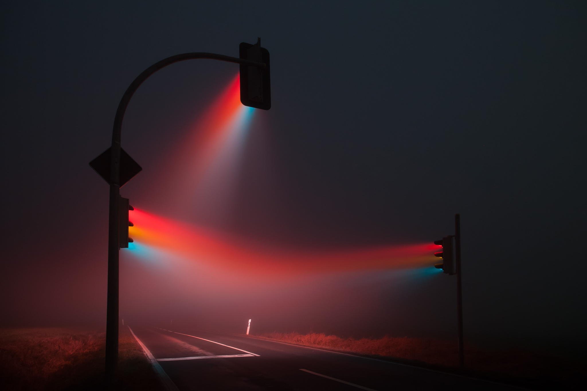
A photograph showing light scattering in heavy fog
Breakdown
So how is it done?
In short, the volume is defined by having two 3D textures. Each texel in the 3D texture represents a
point in the volume.
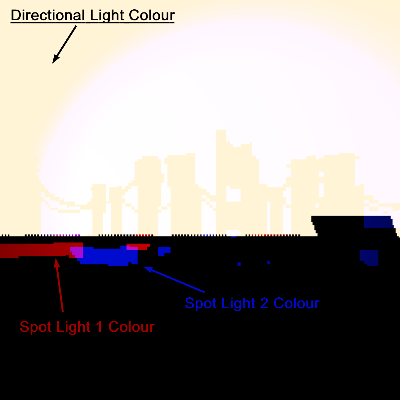
The first texture is responsible for calculating the amount of light for each point in the volume. This
is done by iterating over the number of lights affecting the volume and checking the corresponding
shadow map to see if the light source should affect a given point. Unless the light is occluded the
amount of light is calculated and saved to the texture.The second texture contains the fog density data that represent how much fog there is at a given point
in the volume.Finally, a pixel shader applies the information from both textures by raymarching through the volume,
calculating the colour and density for each point it traverses through, and renders the volume to the
back buffer.
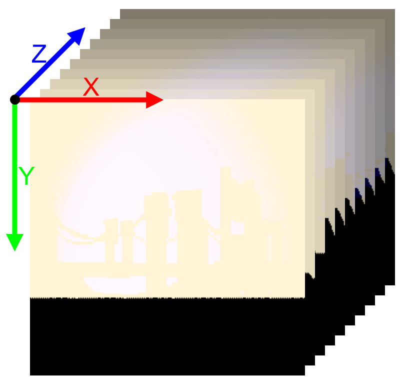
A visualization of how 3D textures works
shadowFactor = CalculateShadowNoBlurring(dLData.shadowMapInfo,
                                        dLData.transform,
                                        worldPosition,
                                        bias);
float3 colour = dLData.directionalLightColour * shadowFactor * dLData.directionalLightIntensity;
for (int i = 0; i < numberOfSL; i++)
{
    SpotLightData light = sLData[i];
    const float3 toCamera = float3(light.transform._14_24_34 - worldPosition);
    shadowFactor = CalculateShadowNoBlurring(light.shadowMapInfo, light.transform, worldPosition, bias);
    const float3 spotlightColour = EvaluateSpotLight(light.colour,
                                                    light.intensity,
                                                    light.range,
                                                    light.position,
                                                    -light.direction,
                                                    light.outerAngle,
                                                    light.innerAngle,
                                                    toCamera,
                                                    worldPosition.xyz);
    const float shadow = shadowFactor * (clamp(1 - length(worldPosition - light.position) / light.range, 0.0f, 1.0f) * light.intensity);
    colour += shadow * spotlightColour;
}
Calculate how much light that reaches a given point in the compute shader. Full example can be found here
Implementation
So, with the knowledge of how this is done, how was it implemented?
First the 3D textures need to be prepared with data. By dispatching the calculations to a compute shader
for each texture I was able to run both calculations in parallel. The texture responsible for the light
data was given information from our deferred rendering pipeline as well as the shadow atlas with all the
relevant light sources data.
The fog density texture estimates its density by generating a perlin noise texture designed to simulate
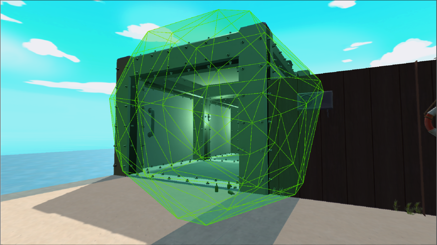
fog. Two external parameters were sent to the compute shaders to simulate wind in any direction.By this point the volume can be rendered as any other model. But there is a problem! When outside of
the volume everything looks correct, but as soon as the camera enters the volume nothing happens. This
happens because when inside the volume we only see back facing triangles and since the renderer is per
default set to only render front facing triangels it therefor doesn’t run the required pixel shader on
the volume.
My solution to this problem was to instead render it with Frontface Culling enabled and not write to
depth. When rendering the volume with these settings the volume instead renders the back faces of the
box. Since depth is not used it is also important to handle the depth calculations manually instead so
that the volume isn’t rendered on top of everything else.
Another solution to this problem is to run the volumes pixel shader as a fullscreen effect
instead.
A slice from the 3D texture containing after calculating how much light reaches a given point.
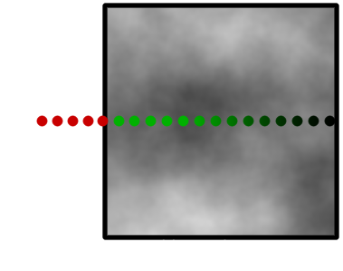
Raymarching?
As mentioned, a pixel shader was used to ray march through the volume. Ray marching is an algorithm where a ray is traversed iteratively by dividing itself into smaller rays and sampling data at each step. In my implementation, each step samples both 3D Textures to see what data correlates to the given point. This is visualized by the green dots in the illustration.By adding the colour given from the light-texture to the fogs colour and multiplying the result with the density value given by the density-texture we are left with a step size contribution to the pixels final colour.
Conclusion
Implementing this has been a real journey. In the beginning I had a hard time finding any concrete sources on how Volumetric Fog has been simulated but after some time I found two really great sources from Bart Wronski (Ubisoft) and Sebastian Hillaire (DICE) that gave me great insight to some AAA versions. I was at first a bit overwhelmed since there was a lot of new subjects for me. Since I had no previous experience with either 3D textures, compute shaders or raymarching I researched a ton before I was confident enough to start.In the end I am happy with the result and I feel like I’ve grown as a programmer from the experience. I am very happy that I got the opportunity to explore compute shaders as I’ve found the subject intriguing but had no reason so far to implement it.If I had more time I would like to tweak how the colours are calculated since I feel like the result can get quite overexposed when a lot of light is directed on the volume. I would also like to implement Temporal Anti-Aliasing since it could help blur the fog since there can be some banding and artifacts from sampling the light texture.
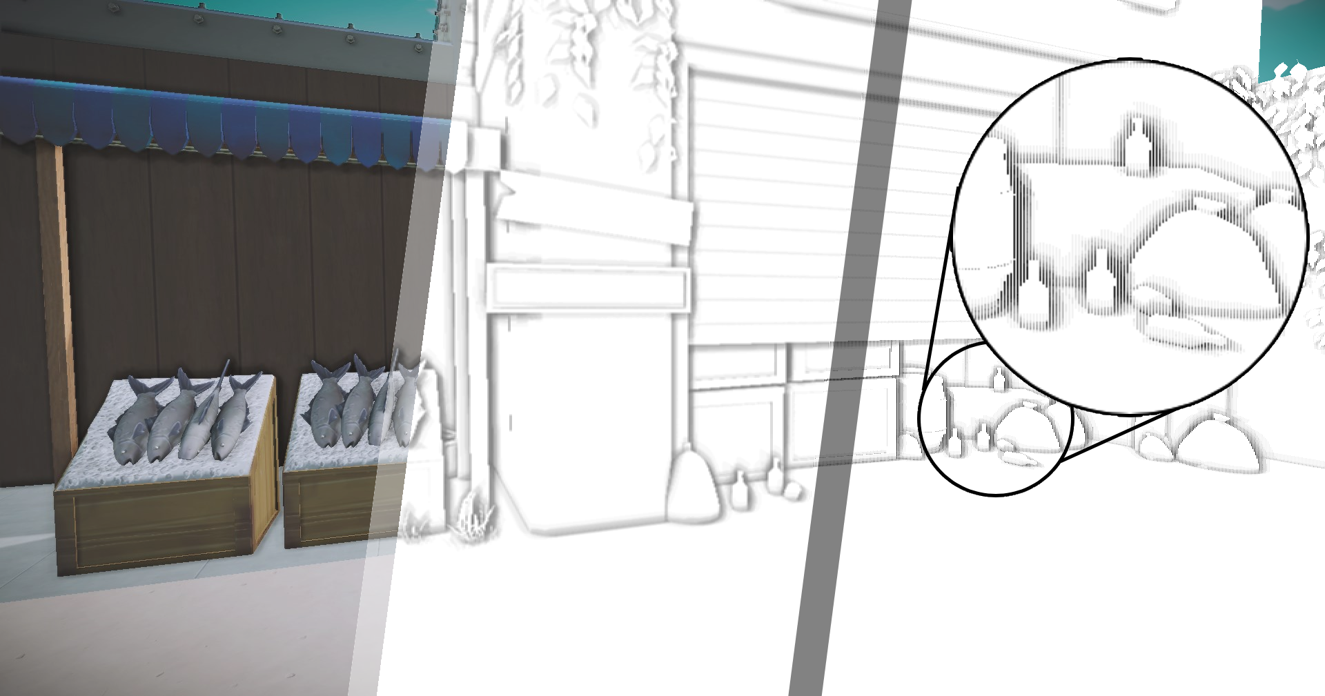
Screen Space Ambient Occlusion
Screen Space Ambient Occlusion, often shortened to SSAO, is a post process technique used to
approximate the ambient occlusion in a 3D-scene to achieve a more realistic result. This is done by
using the scene’s normal vectors and written depth seen from the camera.
SSAO piqued my interest when I was reading about different techniques to improve the visual aspects of
my group’s games as it seemed like a fun and interesting project to take on.
So how is it done?
Since the goal of SSAO is to determine whether a pixel is occluded by other geometry and 3D-models have no way of knowing about other models in the scene, the depth is used to calculate this.When determining the ambient occlusion of a pixel I used precalculated randomized positions in a hemispherical formation facing away from the pixels normal vector. This makes sure that the randomized positions, called sample positions, are facing away from the pixels normal. In the pixel shader I then iterated over every sample position to measure whether the pixel corresponding to the sample positions depth from the camera was greater than the written depth of the same pixel. If it is, the sample is occluded! When every sample has been measured, I returned the average occlusion value.
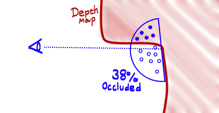
An illustration of how a few random positions inside of a hemisphere can be used to calculate the occlusion of a point.
The result is a rather noisy looking SSAO texture. This is caused by the random vectors used to create the TBN matrix that is created to move the sample position in the hemisphere to the pixels world space position. To fix the noise pattern I used a pixel shader to blur the texture into the result below.
for (int i = 0; i < SSAONumOfSamples; i++)
{
    float3 samplePos = mul(SSAOSamples[i].xyz, TBN);
    samplePos = worldPos.xyz + samplePos * rad;

    const float4 offset = mul(worldToClipSpaceMatrix, float4(samplePos, 1.0f));
    const float3 sampledProjectedPos = offset.xyz / offset.w;
    const float2 sampleUV = 0.5f + float2(0.5f, -0.5f) * sampledProjectedPos.xy;
    const float sampleDepth = depthTex.Sample(SSAOSampler, sampleUV.xy).r;
    const float3 sampledWP = worldPositionTex.Sample(SSAOSampler, sampleUV.xy).xyz;
    const float pixelDist = length(worldPos.xyz - sampledWP);
    const float rangeCheck = smoothstep(0.0f, 1.0f, rad / pixelDist);

    occlusion += (sampleDepth < sampledProjectedPos.z - bias ? 1.0f : 0.0f) * rangeCheck;
}
occlusion = 1.0f - (occlusion / SSAONumOfSamples);
output.aoTexture = float4(occlusion, occlusion, occlusion, 1);
return output;
Part of the pixel shader, all code can be found here
The Final Result:
The final image is later used to calculate the ambient lighting of the scene together with the ambient occlusion texture generated by our artists. The result increases the realism of the image by adding a relationship between each object in the scene. Overall I am very pleased with the result.
Whats next?
At the moment my implementation is quite expensive performance-wise. At full HD resolution it takes roughly ~16.5 ms with 16 samples per pixel at full HD in debug which is unacceptable. To make this a bit cheaper I would like to move from a pixel shader to a compute shader to see if it increases performance. Another optimization would be to run the sample shader on a smaller resolution and then to upscale it to fit the screen.
Group Projects
Intergalactic Ball Throwing Championship With Friends ツ
Genre: Couch multiplayer
Timeframe: 8 Weeks (40h/week)
Team: 4 programmers, 4 artists, 1 level designer
Engine: Custom Engine (Kitty Engine)
My Contributions:
Dynamic Camera System
Build Export System
Lobby System (character selection)
Cheat Code System
Multi Scene Export System
Harbor Havoc
Genre: First Person Tower Defense Shooter
Timeframe: 15 weeks (20h/week)
Team: 6 programmers, 4 artists, 1 level designer
Engine: Custom Engine (Kitty Engine)
My Contributions:
Implemented PhysX
SSAO
Game State Handling
Minor Gameplay Features
Spite - Hymn of Hate
Genre: Action RPG
Timeframe: 10 weeks (20h/week)
Team: 6 programmers, 5 artists, 3 level designers
Engine: Custom Engine (Kitty Engine)
My Contributions:
Deferred Rendering
Lights and shadows
More Advanced Gameobject Component System
Boss Fight State Handling
Custom Binary file formats for navmesh and level settings
A Brush With Death
Genre: First Person Point & Click
Timeframe: 4 weeks (20h/week)
Team: 6 programmers, 5 artists, 3 level designers
Engine: Custom Engine (Kitty Engine)
My Contributions:
Basic Gameobject Component System
Basic Collision System
Game Loop
Scene Management
Post Process

Stella’s Quest
Genre: Adventure Game
Timeframe: 8 weeks (20h/week)
Team: 6 programmers, 4 artists, 3 level designers
Engine: Custom Engine (Kitty Engine)
My Contributions:
Enemy AI
Droppable Loot
Voice Acting